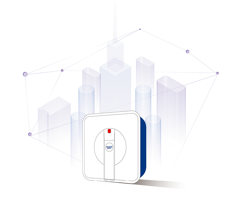
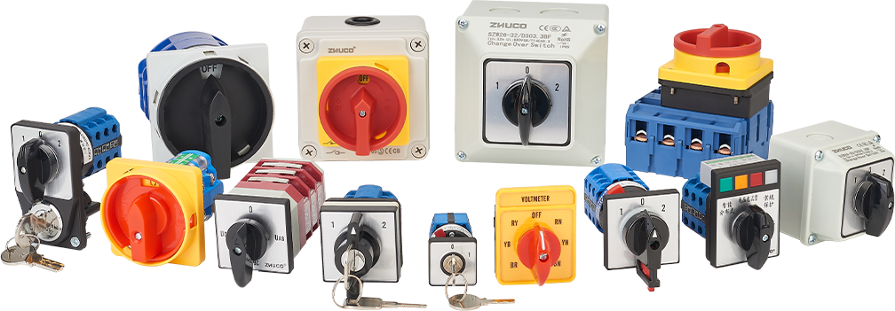
Since 2000, we have been delivering reliable fluid handling solutions for power systems, mechanical automation, and industrial processing.
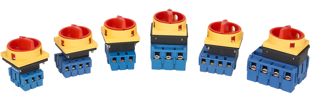
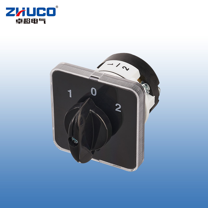
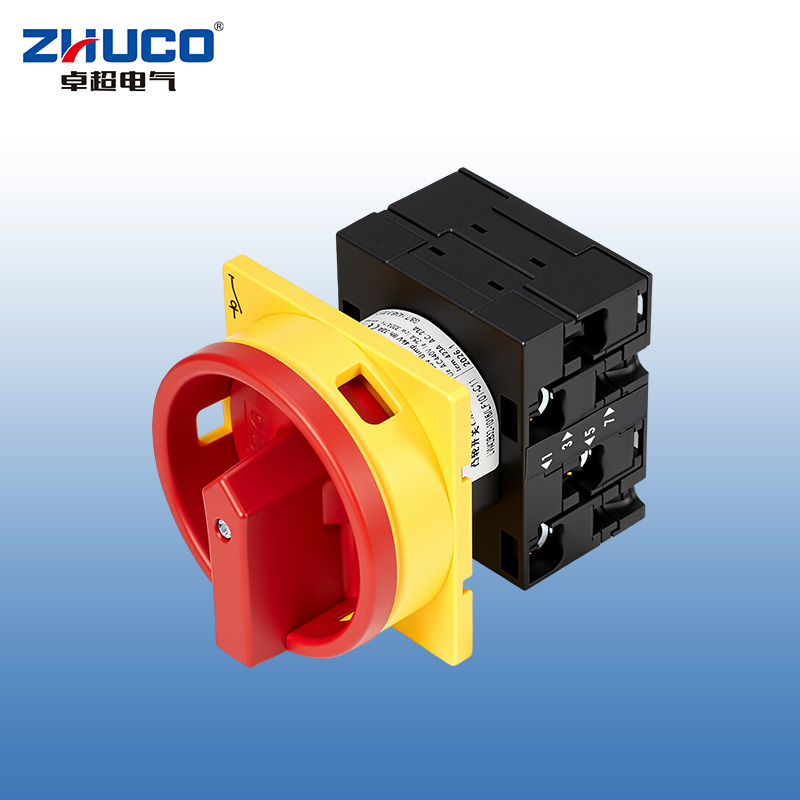
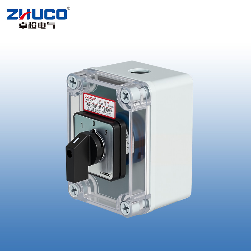
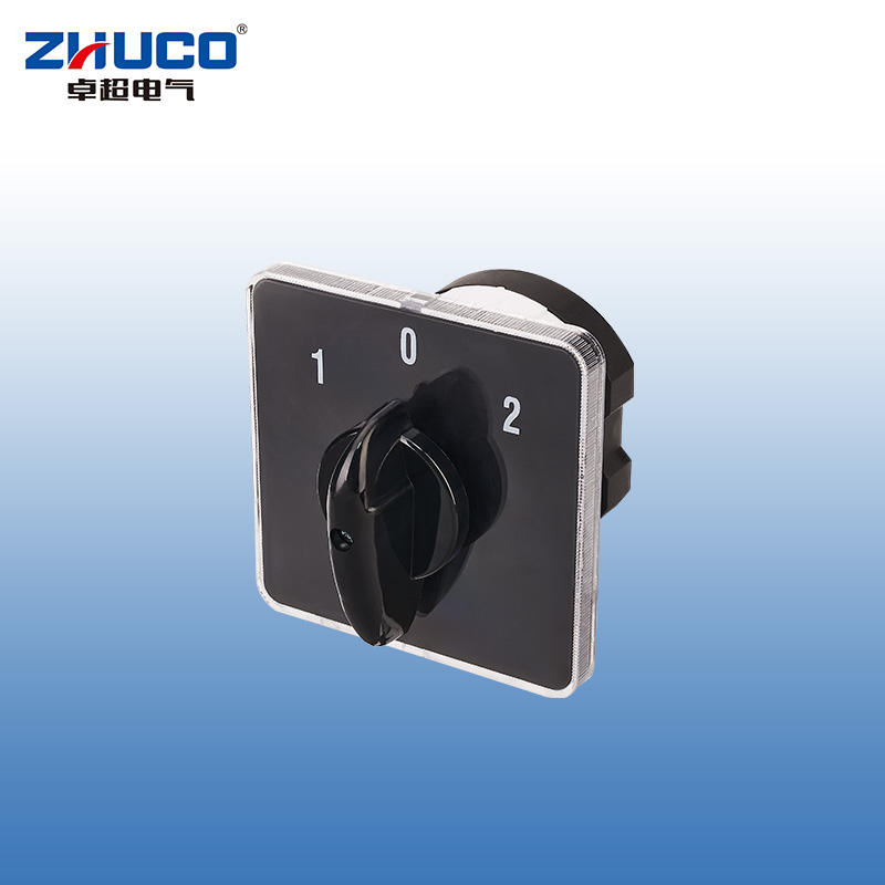
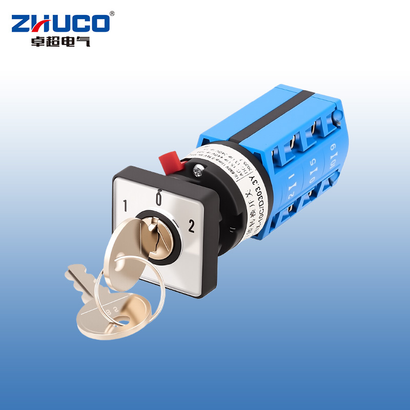
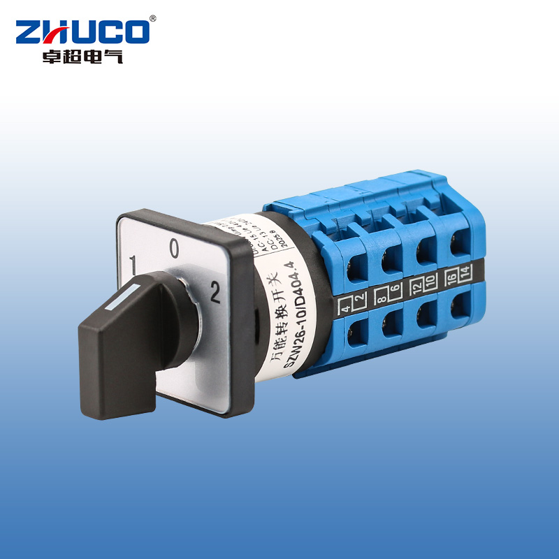
The SZL9-20/D0083.1 has a rated current of 20A and features a single-pole, three-position design. One power input is split into two power outputs, allowing for switching between two devices. Position 1 connects the first set of L terminals, position 2 connects the second set of L terminals, and the middle position O disconnects both. It is suitable for AC 50Hz~60Hz electrical circuits with a rated operating voltage of ≤440V and a rated insulation voltage of 690V. The switch has a compact structure, clear operation, and a reasonable position layout. Its contact design emphasizes conductive stability. The product is suitable for general electrical control systems, meeting daily equipment operation needs. It offers flexible installation options and can be used in distribution boxes and control cabinets.
It uses flame-retardant, high-temperature-resistant, and environmentally friendly materials with good insulation properties.
Thickened copper components and silver alloy contacts provide excellent conductivity, oxidation resistance, safety, and durability.
Mechanical life: 0.3 x 10⁶ cycles, operating frequency 120 cycles/hour.
Electrical life: 0.6 x 10⁶ cycles, operating frequency 120 cycles/hour.
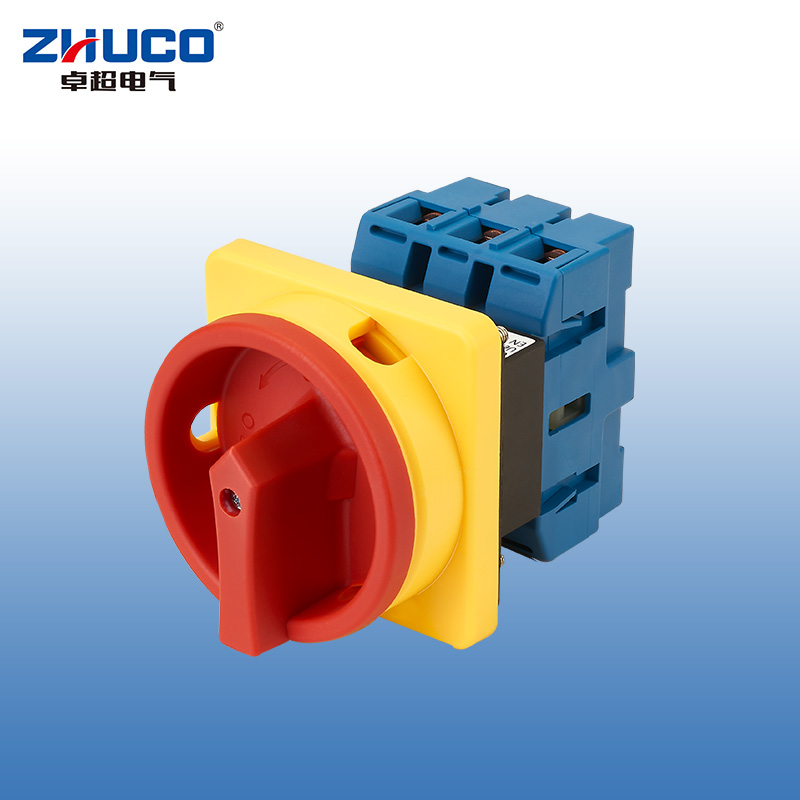
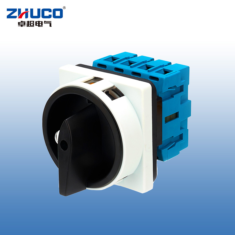
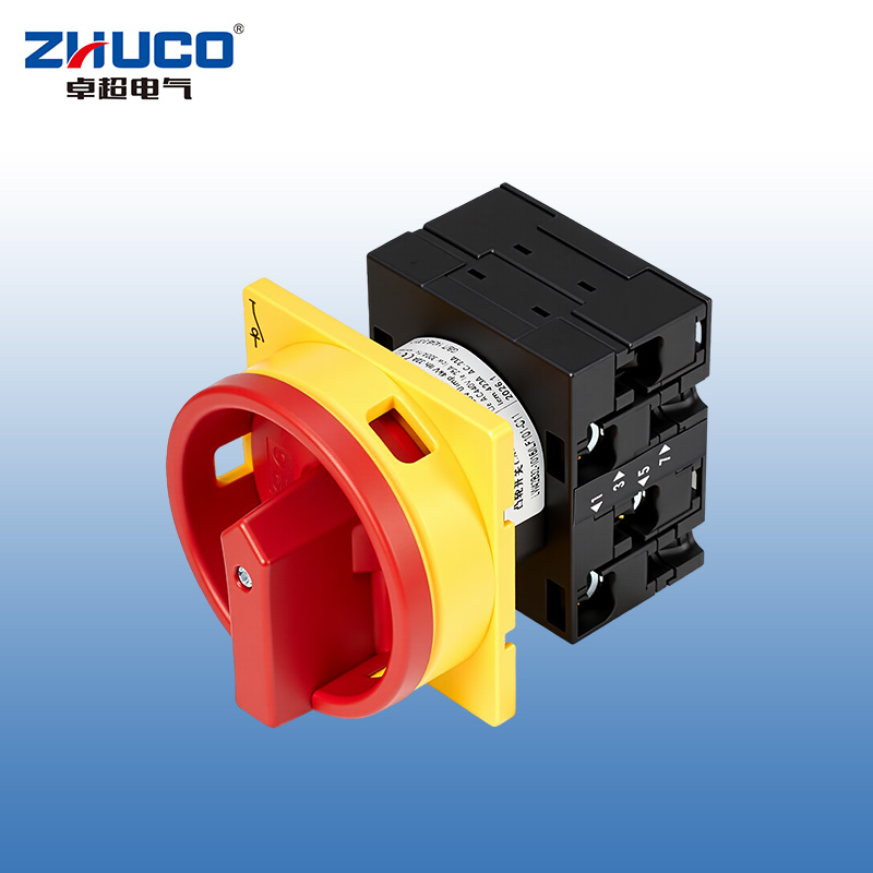
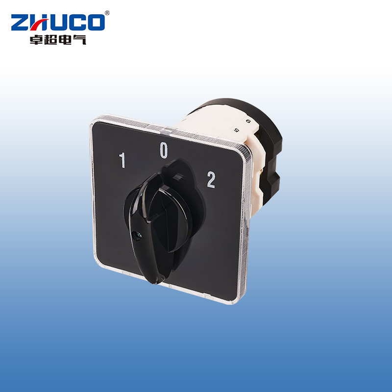
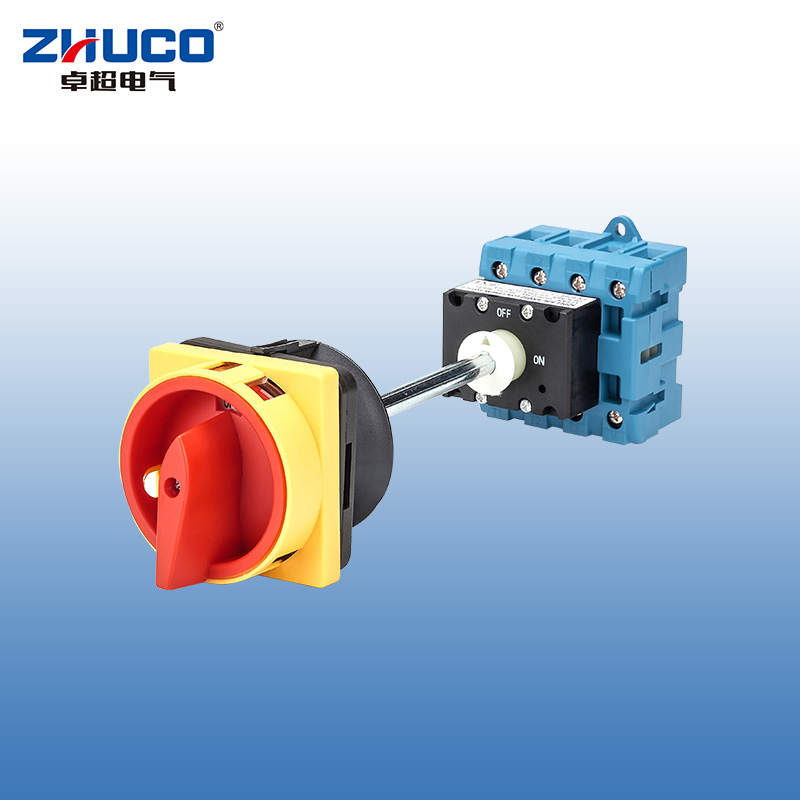
The SZD11-40/30001U is a manual load disconnect switch designed specifically for three-phase (3P) power circuits, with a rated current of 40A. This panel-mounted product integrates a safety padlock function, providing a reliable manual operation and mechanical locking solution for power isolation, load switching, and maintenance safety of electrical equipment. Its design complies with relevant safety standards and is suitable for applications requiring clearly defined disconnection points and operational access control.
Rated operating current: 40A
Rated operating voltage: AC 440V, 50Hz-60Hz
Number of poles: 3P (three-phase)
Compliance standards: GB/T 14048.3, IEC 60947-3
On/off function: Two-position (ON/OFF) operation.
ON position: All three-phase main contacts (T1-L1, T2-L2, T3-L3) are reliably connected.
OFF position: All main contacts are completely disconnected, providing a visible electrical isolation point that meets safety distance requirements.
Safety Locking: A padlock hole (locker sold separately) is provided in the OFF position for mechanical locking to prevent unauthorized or accidental operation.
Installation Method: Panel mounting, easy to install and operate on control cabinets, distribution box doors, or equipment surfaces.
Performance Characteristics: Offers greater insulation distance and faster disconnection capability than similar products, improving operational safety and electrical reliability.
Wiring Capacity: M4 terminal screw specification, suitable for conductor cross-sectional area 6.0 ~ 10 mm², recommended tightening torque 1.2 N·m.
Rated Duty Cycle: 8-hour duty cycle/intermittent periodic duty, operating frequency: ≤ 30 times/hour.
Electrical Life: AC-23 (resistive load, distribution) service category: ≥ 10,000 cycles. AC-3 (cage motor load) service category: ≥ 6,000 cycles.
Operating Conditions:
Ambient Temperature: -25°C to +40°C (average temperature ≤ +35°C over 24 hours). Altitude: ≤ 2000 m.
Relative Humidity: Not exceeding 50% at +40°C; up to 90% at lower temperatures (e.g., +20°C) (protective measures must be taken to prevent condensation).
This switch is specifically designed for industrial and commercial electrical circuits requiring manual switching and safety isolation of three-phase loads, and is installed on an operating panel.
Main Power Switch and Maintenance Isolation Point: Serves as the main power isolation switch for three-phase equipment such as ventilation equipment, air conditioning units, water pumps, and compressors with a rated current not exceeding 40A. Its lockable function provides a safe electrical isolation and locking point for equipment maintenance.
Manual Operation Switch for Control Cabinets: Installed on the operating panel of industrial control cabinets and distribution boxes, it serves as a local manual control switch for loads such as fans, motors, and heating equipment, facilitating direct and safe start-up and shutdown operations by operators.
Safety Distribution Circuit Isolation: Used as a manual isolating switch in distribution branch circuits requiring a clearly defined physical disconnection point for safe isolation during load switching and maintenance.
Direct control of small-capacity motors: control circuits that can be directly used for small-capacity three-phase asynchronous motors that are not frequently started and stopped (AC-3 load category).
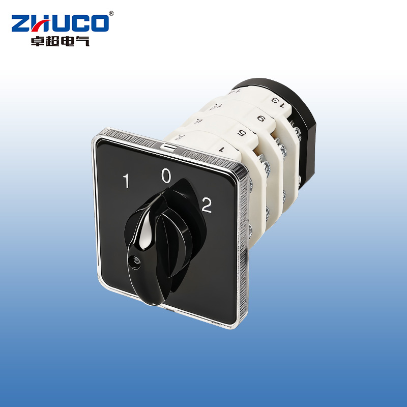
The SZD11-25/400010 is a three-phase four-wire (3P+N) manual load disconnector with a rated current of 25A. It is panel-mounted and has a gray-black casing. Its core function is to provide safe and reliable connection and isolation for AC three-phase four-wire systems (including the neutral line), and it is equipped with a padlock mechanism in the OFF position to prevent accidental operation and meet safety operating procedures.
Core Parameters and Characteristics:
Rated Values: Rated operating current 25A, rated operating voltage AC 440V, 50Hz-60Hz.
Compliant Standards: GB/T 14048.3, IEC 60947-3.
Number of Poles and Functions: 4 poles (3P+N). Handle Operation: Two Positions (ON/OFF):
ON Position: All three-phase main contacts (T1-L1, T2-L2, T3-L3) and the neutral pole (N) are connected.
OFF Position: All poles (3P+N) are fully disconnected, providing complete electrical isolation. A padlock (sold separately) can be added in this position for mechanical locking.
Construction and Installation: Panel mounted with a gray-black panel handle. Features a large insulation distance and quick-break design for enhanced operational safety and reliability.
Wiring and Lifespan:
Wiring: M3.5 screws, wire diameter 2.5 – 6.0 mm², tightening torque 0.8 N·m.
Operating Frequency: 8-hour duty cycle/intermittent cycle duty, operating frequency 30 times/hour.
Electrical Life: ≥ 10,000 cycles under AC-23 category; ≥ 6,000 cycles under AC-3 category; auxiliary contacts ≥ 2,000 cycles.
Operating Conditions: Ambient temperature -25°C to +40°C, altitude ≤ 2000m.
Application Scenarios
This switch is suitable for applications requiring safe switching, isolation, and locking of small to medium power three-phase four-wire loads, and is a key component ensuring safe equipment maintenance.
Main Power Switch for Small and Medium-Sized Equipment: As a main power isolating switch for three-phase four-wire equipment such as commercial air conditioners, ventilation equipment, water pumps, and small processing equipment with a rated current not exceeding 25A, its four-pole disconnection ensures complete isolation between the phase and neutral lines.
Safety Isolation Point in Distribution Boxes: In distribution boxes in commercial locations, laboratories, and small factories, it serves as a branch circuit isolating switch requiring complete electrical isolation, particularly suitable for TN-S or TN-C-S systems where the neutral line needs to be disconnected for safe maintenance.
Safety Lockout (LOTO) Applications: The padlock function in the OFF position makes it ideal for implementing lockout and tagging safety procedures, providing reliable protection for maintenance personnel, and suitable for facilities requiring compliance management.
Direct Control and Local Operation: It can be used for direct control of small-capacity three-phase motors (AC-3 loads) that are not frequently operated, and can be installed on a control panel for easy local safe operation.
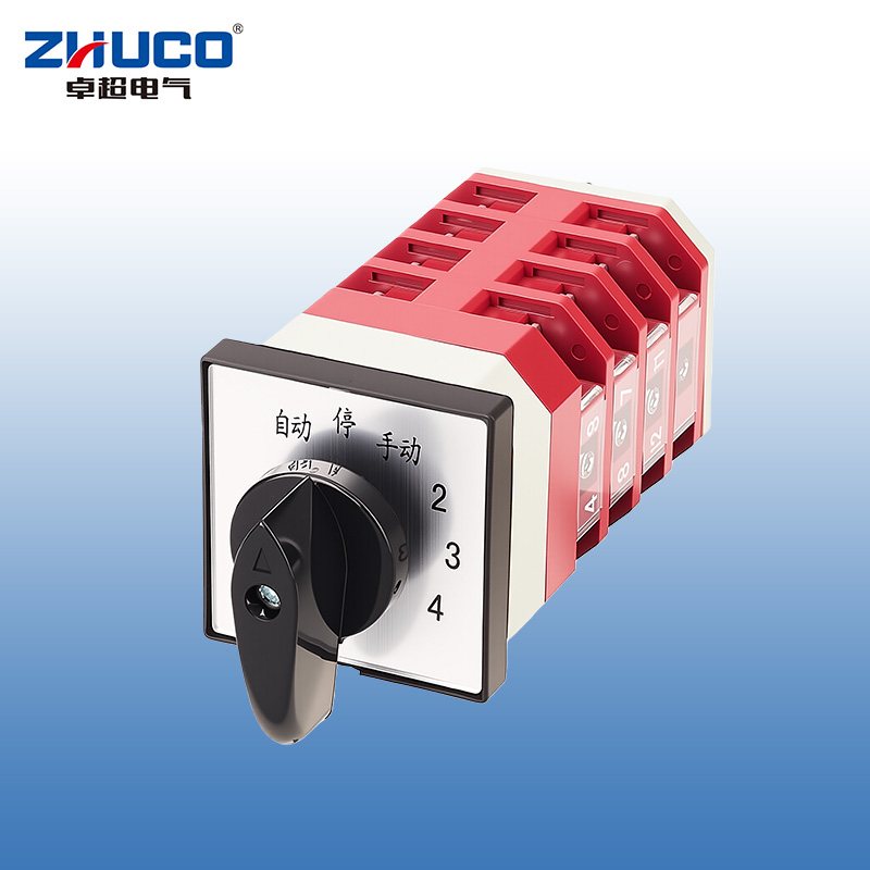
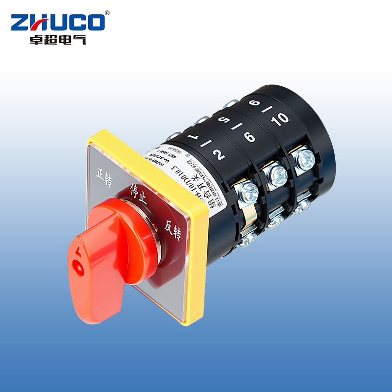
The LW12-16/TM704.4 is a four-circuit step-change switch specifically designed for low-voltage reactive power compensation capacitor banks. Its core function is as a manual standby and adjustment unit for an automatic power factor controller. By rotating the handle, up to four parallel capacitor branches can be manually connected or disconnected in steps (0→1→2→3→4), thus achieving precise and reliable adjustment of the system's reactive power. The switch panel features clear "automatic-stop-manual" mode selection and digital scale indicators, making operation intuitive and status readily apparent.
2. Main Technical Parameters and Characteristics
Rated Insulation Voltage: 690V
Rated Operating Voltage: AC ≤ 500V 50Hz-60Hz; DC ≤ 220V
Conventional Free Air Heating Current (Ith): 16A
Rated Control Capacity: AC-15: 240V·A; DC-13: 24W
Motor Control: Can directly control three-phase AC squirrel-cage induction motors (AC-3) of 5.5kW and below.
Contact Configuration and Operating Logic (Based on Wiring Diagram)
Structure: Four-section (four-layer) contact group, achieving five-level step logic through a dedicated cam assembly.
Mechanical and Life Parameters
Mechanical Life: ≥ 30,000 cycles (operation frequency ≤ 120 cycles/hour)
Electrical Life:
AC-15 (Controlling electromagnets, etc.): ≥ 10,000 cycles (300 cycles/hour)
DC-13 (Controlling DC electromagnetic loads): ≥ 10,000 cycles (300 cycles/hour)
AC-3 (Controlling three-phase motors): ≥ 10,000 cycles (120 cycles/hour)
AC-4 (Inching, reverse braking): ≥ 1,000 cycles (120 cycles/hour)
Wiring and Installation
Terminals: Screw specification M4, connecting wire range 1.0 - 2.5 mm², tightening torque 1.2 N·m.
Appearance and Packaging: Single unit weight approximately 0.253 kg; standard packaging 100 units/box.
Materials and Safety
Uses a flame-retardant, high-temperature resistant, environmentally friendly shell with excellent insulation performance.
Internally, it uses thickened copper conductors and silver alloy contacts, providing excellent conductivity, oxidation resistance, and durability.
3. Application Scenarios
This switch is a key manually operated component in the reactive power compensation stage of low-voltage power distribution systems, primarily used in the following scenarios:
Core Application: Low-voltage reactive power compensation capacitor bank
Standby Adjustment: When the automatic power factor controller (PPC) malfunctions, is under maintenance, or is being debugged, switching to "manual" mode allows for tiered switching of capacitor banks, maintaining the system power factor, ensuring power quality, and avoiding power factor adjustment penalties.
Fixed Compensation: In situations where the load is stable and frequent automatic adjustments are not required, it can be directly set to a fixed manual compensation level.
Maintenance and Debugging: Provides electrical personnel with clear capacitor switching instructions and an operating interface, facilitating system debugging, troubleshooting, and maintenance.
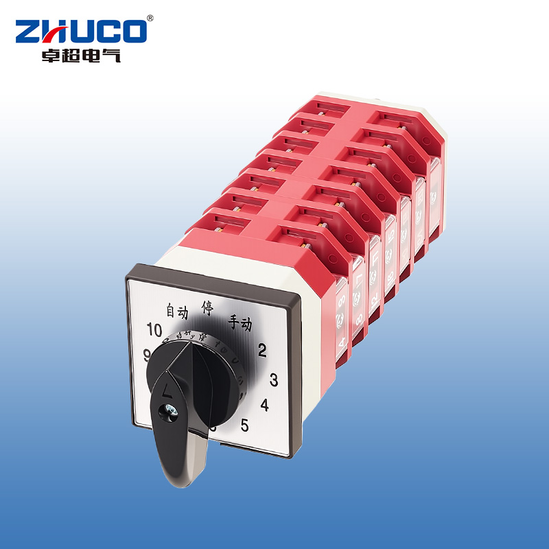
The LW12-16/TM707.7 is a ten-circuit step-change switch designed for low-voltage reactive power compensation systems. As the core manual control unit of the capacitor bank, it allows for precise manual adjustment of the system power factor by rotating a handle in ten steps (0 to 10) when the automatic compensation device fails or precise intervention is required. The product features a red and white color scheme, and the panel integrates "automatic-stop-manual" mode selection and a clear 0-10 digital scale, making operation intuitive and providing clear status indications.
1. Main Technical Parameters and Characteristics
Electrical Parameters
Rated Insulation Voltage: 690V
Rated Operating Voltage: AC ≤ 500V 50Hz-60Hz; DC ≤ 220V
Conventional Free Air Heating Current (Ith): 16A
Rated Control Capacity: AC-15: 240V·A; DC-13: 24W
Motor Control Capability: Can directly control three-phase AC squirrel-cage induction motors of 5.5kW and below (AC-3 application category).
Contact Configuration and Operating Logic (Based on TM707.7 Wiring Table) Structure: Employs a multi-section (layer) contact combination, achieving precise switching of eleven positions (position 0 + 10 active positions) through a precision cam mechanism.
Positions and Functions:
"Auto" Position (Leftmost): Switch exits manual control circuit; system is managed by an external automatic power factor controller (PPC).
"Stop" Position (Middle 0°): All contacts are open (0-way active), providing complete electrical isolation.
"Manual" Adjustment Position (clockwise 30° to 300°): Rotate the black knob; the pointer moves along the dial from "1" to "10". According to the wiring diagram (X represents "on"), each step adds a new set of corresponding contact circuits, thus sequentially connecting one capacitor, until all ten circuits are connected.
Waywiring Diagram Interpretation Example: In "Manual 1" position (clockwise 30°), contact group 1 is connected; in "Manual 2" position (clockwise 60°), contact groups 1 and 2 are connected; and so on, achieving cumulative step-by-step connection.
Mechanical, Lifespan, and Installation Parameters
Mechanical Lifespan: ≥ 30,000 cycles (operating frequency ≤ 120 cycles/hour)
Electrical Lifespan:
AC-15: ≥ 10,000 cycles (300 cycles/hour)
DC-13: ≥ 10,000 cycles (300 cycles/hour)
AC-3: ≥ 10,000 cycles (120 cycles/hour)
AC-4: ≥ 1,000 cycles (120 cycles/hour)
Wiring Specifications: Screw M4, wire 1.0-2.5mm², tightening torque 1.2 N·m.
Installation Dimensions: Mounting hole spacing 45mm × 45mm; applicable panel thickness 1-5mm.
Physical Parameters: Single unit weight approximately 0.355kg.
Materials and Processes: Flame-retardant, high-temperature resistant, and environmentally friendly shell with reliable insulation performance.
Internally, thickened copper components and silver alloy contacts ensure low contact resistance, high conductivity, strong oxidation resistance, and a long service life.
2. Application Scenarios
This switch is specifically designed for applications requiring multi-stage, high-capacity reactive power compensation. It serves as an important backup and manual adjustment unit in automatic compensation systems.
Core Application: Large and medium-sized low-voltage reactive power compensation capacitor banks
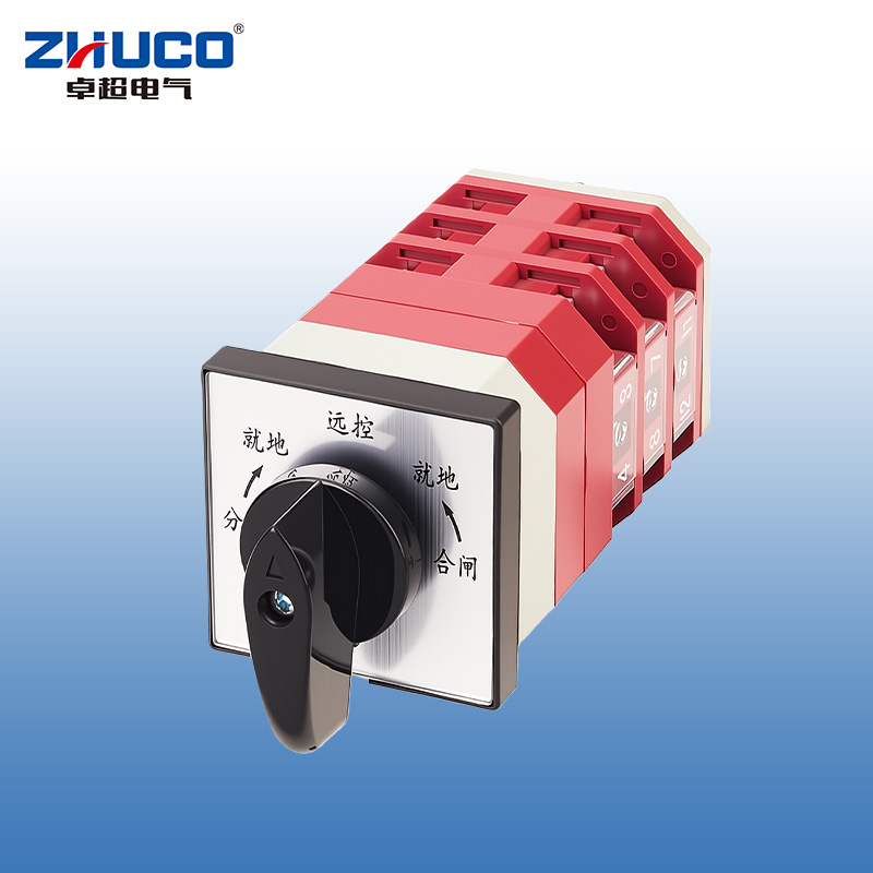
The LW12-16/Z4.5858.3 is a reset-type control transfer switch specifically designed for the opening and closing operations of primary equipment such as high-voltage circuit breakers and load switches in power transmission and distribution systems. Its core function is to safely switch between "local" and "remote" control locations, executing "open" and "close" commands respectively. The switch features an automatic reset design to the intermediate "remote control" position (the handle automatically resets after local operation), ensuring that control is automatically returned to the remote system after completing local emergency operations, preventing accidental retention in local mode, thus greatly improving operational safety and system management standardization. Its red and white color scheme and clear panel markings facilitate quick identification and operation in environments such as power distribution rooms.
1. Main Technical Parameters and Functional Characteristics
Electrical Parameters
Rated Insulation Voltage: 690V
Rated Operating Voltage: AC ≤ 500V 50Hz-60Hz; DC ≤ 220V
Conventional Free Air Heating Current (Ith): 16A
Control Capacity: Suitable for control circuits and signal indications; can directly control three-phase asynchronous motors of 5.5kW and below.
Operating Functions and Contact Logic (Based on Wiring Table)
Position and Contact Action (X indicates ON):
Operating Mode: Select "Local" or "Remote" mode via the black knob on the panel; execute "Open" or "Close" commands via the black operating handle on the side.
Remote Control: Handle in the middle position. In this position, the switch contact state depends on the remote signal; the local handle does not operate directly.
Mechanical, Lifespan, and Structural Parameters
Mechanical Lifespan: ≥ 30,000 cycles
Electrical Lifespan:
AC-15 (Controls electromagnetic loads): ≥ 10,000 cycles
DC-13 (Controls DC electromagnetic loads): ≥ 10,000 cycles
AC-3 (Controls motors): ≥ 10,000 cycles
AC-4 (Inching, Reverse Braking): ≥ 1,000 cycles
Wiring Capacity: M4 wiring screws, 1.0-2.5mm² wires, tightening torque 1.2 N·m.
Materials and Manufacturing Process: Flame-retardant and high-temperature resistant shell, thickened copper parts, silver alloy contacts, ensuring safety and durability.
Physical Parameters: Single weight approximately 0.25 kg.
2. Application Scenarios
This switch is a key component in power systems for safely switching between local and remote control permissions, specifically designed for applications requiring strict operating procedures and prevention of misoperation.
Core Applications: High and Low Voltage Switchgear Control Circuits
Circuit Breaker/Load Switch Control: Installed on the door panel of high-voltage switchgear, ring main units, and low-voltage distribution cabinets, serving as an authorized interface for local operation/maintenance. Maintenance or repair personnel must switch the knob to the "Local" position to perform opening and closing operations. Automatic reset is performed after operation to prevent forgetting to leave the local mode.
Control Access Management: Under normal operation, it is placed in the "Remote Control" position for automatic control by SCADA, DCS, or relay protection devices. During on-site commissioning, maintenance, or emergency operations, it switches to the "Local" position for safe and reliable manual intervention.
Typical Use Cases
Substations and Distribution Stations: Used for control panels of transformers, incoming and outgoing line cabinets, bus tie cabinets, etc.
Industrial and Mining Enterprise Power Distribution Rooms: Serves as a backup manual control point for critical power distribution equipment such as large motors and capacitor compensation devices.
Power Automation Systems: Serves as a backup manual interface and maintenance isolation point for automation control, ensuring safe operation even in the event of automation system failure.
Founded in
Floor area
Employees
Certificates
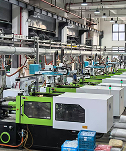
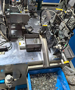
Advanced production equipment: Adopt high-precision intelligent production equipment to achieve automated operations and high production efficiency.
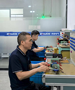
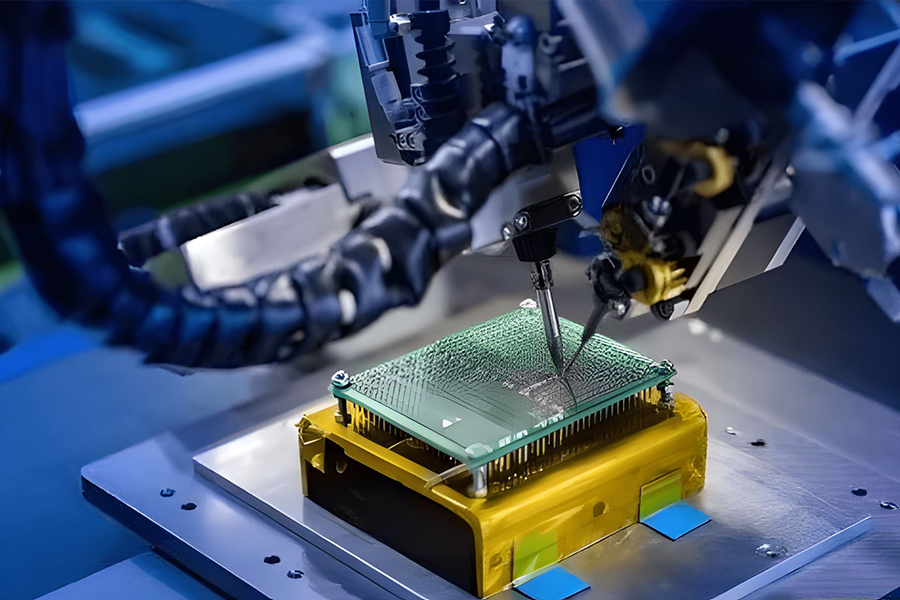
Precision testing instruments: Equipped with a full set of precision testing equipment to control product quality and accuracy throughout the entire process.
High-tech process flows: Digital and intelligent production processes, balancing efficiency, customization and environmental friendliness.
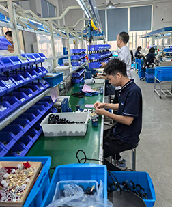
Senior technical talents: Gather an experienced technical team to provide core technical support and program optimization.
Automated workshop: Full-process automated production to improve efficiency, reduce defect rates and ensure stable output.