English
 русский
 Español
 Deutsch
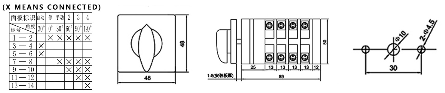
The LW12-16/TM704.4 is a four-circuit step-change switch specifically designed for low-voltage reactive power compensation capacitor banks. Its core function is as a manual standby and adjustment unit for an automatic power factor controller. By rotating the handle, up to four parallel capacitor branches can be manually connected or disconnected in steps (0→1→2→3→4), thus achieving precise and reliable adjustment of the system's reactive power. The switch panel features clear "automatic-stop-manual" mode selection and digital scale indicators, making operation intuitive and status readily apparent.
2. Main Technical Parameters and Characteristics
Rated Insulation Voltage: 690V
Rated Operating Voltage: AC ≤ 500V 50Hz-60Hz; DC ≤ 220V
Conventional Free Air Heating Current (Ith): 16A
Rated Control Capacity: AC-15: 240V·A; DC-13: 24W
Motor Control: Can directly control three-phase AC squirrel-cage induction motors (AC-3) of 5.5kW and below.
Contact Configuration and Operating Logic (Based on Wiring Diagram)
Structure: Four-section (four-layer) contact group, achieving five-level step logic through a dedicated cam assembly.
Mechanical and Life Parameters
Mechanical Life: ≥ 30,000 cycles (operation frequency ≤ 120 cycles/hour)
Electrical Life:
AC-15 (Controlling electromagnets, etc.): ≥ 10,000 cycles (300 cycles/hour)
DC-13 (Controlling DC electromagnetic loads): ≥ 10,000 cycles (300 cycles/hour)
AC-3 (Controlling three-phase motors): ≥ 10,000 cycles (120 cycles/hour)
AC-4 (Inching, reverse braking): ≥ 1,000 cycles (120 cycles/hour)
Wiring and Installation
Terminals: Screw specification M4, connecting wire range 1.0 - 2.5 mm², tightening torque 1.2 N·m.
Appearance and Packaging: Single unit weight approximately 0.253 kg; standard packaging 100 units/box.
Materials and Safety
Uses a flame-retardant, high-temperature resistant, environmentally friendly shell with excellent insulation performance.
Internally, it uses thickened copper conductors and silver alloy contacts, providing excellent conductivity, oxidation resistance, and durability.
3. Application Scenarios
This switch is a key manually operated component in the reactive power compensation stage of low-voltage power distribution systems, primarily used in the following scenarios:
Core Application: Low-voltage reactive power compensation capacitor bank
Standby Adjustment: When the automatic power factor controller (PPC) malfunctions, is under maintenance, or is being debugged, switching to "manual" mode allows for tiered switching of capacitor banks, maintaining the system power factor, ensuring power quality, and avoiding power factor adjustment penalties.
Fixed Compensation: In situations where the load is stable and frequent automatic adjustments are not required, it can be directly set to a fixed manual compensation level.
Maintenance and Debugging: Provides electrical personnel with clear capacitor switching instructions and an operating interface, facilitating system debugging, troubleshooting, and maintenance.