English
 русский
 Español
 Deutsch
The LW12-16/TM707.7 is a ten-circuit step-change switch designed for low-voltage reactive power compensation systems. As the core manual control unit of the capacitor bank, it allows for precise manual adjustment of the system power factor by rotating a handle in ten steps (0 to 10) when the automatic compensation device fails or precise intervention is required. The product features a red and white color scheme, and the panel integrates "automatic-stop-manual" mode selection and a clear 0-10 digital scale, making operation intuitive and providing clear status indications.
1. Main Technical Parameters and Characteristics
Electrical Parameters
Rated Insulation Voltage: 690V
Rated Operating Voltage: AC ≤ 500V 50Hz-60Hz; DC ≤ 220V
Conventional Free Air Heating Current (Ith): 16A
Rated Control Capacity: AC-15: 240V·A; DC-13: 24W
Motor Control Capability: Can directly control three-phase AC squirrel-cage induction motors of 5.5kW and below (AC-3 application category).
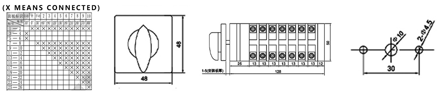
Contact Configuration and Operating Logic (Based on TM707.7 Wiring Table) Structure: Employs a multi-section (layer) contact combination, achieving precise switching of eleven positions (position 0 + 10 active positions) through a precision cam mechanism.
Positions and Functions:
"Auto" Position (Leftmost): Switch exits manual control circuit; system is managed by an external automatic power factor controller (PPC).
"Stop" Position (Middle 0°): All contacts are open (0-way active), providing complete electrical isolation.
"Manual" Adjustment Position (clockwise 30° to 300°): Rotate the black knob; the pointer moves along the dial from "1" to "10". According to the wiring diagram (X represents "on"), each step adds a new set of corresponding contact circuits, thus sequentially connecting one capacitor, until all ten circuits are connected.
Waywiring Diagram Interpretation Example: In "Manual 1" position (clockwise 30°), contact group 1 is connected; in "Manual 2" position (clockwise 60°), contact groups 1 and 2 are connected; and so on, achieving cumulative step-by-step connection.
Mechanical, Lifespan, and Installation Parameters
Mechanical Lifespan: ≥ 30,000 cycles (operating frequency ≤ 120 cycles/hour)
Electrical Lifespan:
AC-15: ≥ 10,000 cycles (300 cycles/hour)
DC-13: ≥ 10,000 cycles (300 cycles/hour)
AC-3: ≥ 10,000 cycles (120 cycles/hour)
AC-4: ≥ 1,000 cycles (120 cycles/hour)
Wiring Specifications: Screw M4, wire 1.0-2.5mm², tightening torque 1.2 N·m.
Installation Dimensions: Mounting hole spacing 45mm × 45mm; applicable panel thickness 1-5mm.
Physical Parameters: Single unit weight approximately 0.355kg.
Materials and Processes: Flame-retardant, high-temperature resistant, and environmentally friendly shell with reliable insulation performance.
Internally, thickened copper components and silver alloy contacts ensure low contact resistance, high conductivity, strong oxidation resistance, and a long service life.
2. Application Scenarios
This switch is specifically designed for applications requiring multi-stage, high-capacity reactive power compensation. It serves as an important backup and manual adjustment unit in automatic compensation systems.
Core Application: Large and medium-sized low-voltage reactive power compensation capacitor banks